Cutaways of 143 VVC exhaust ports (picture heavy)
Last year I posted this note on the inlet ports of the VVC head:
http://forums.mg-rover.org/showthread.php?t=503432
This is the follow up, although the sections are not as exciting - Exhausts rarely are.
The sections are the opposites to the inlets in that thread:
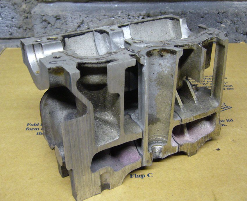
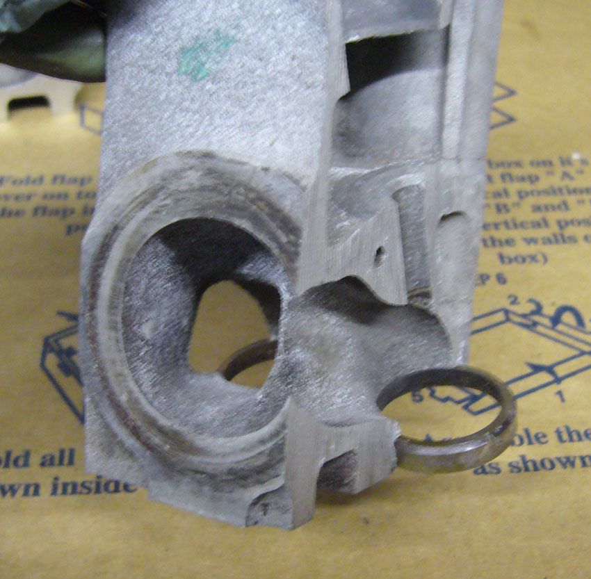
The first section is the one on the cam pulley end.
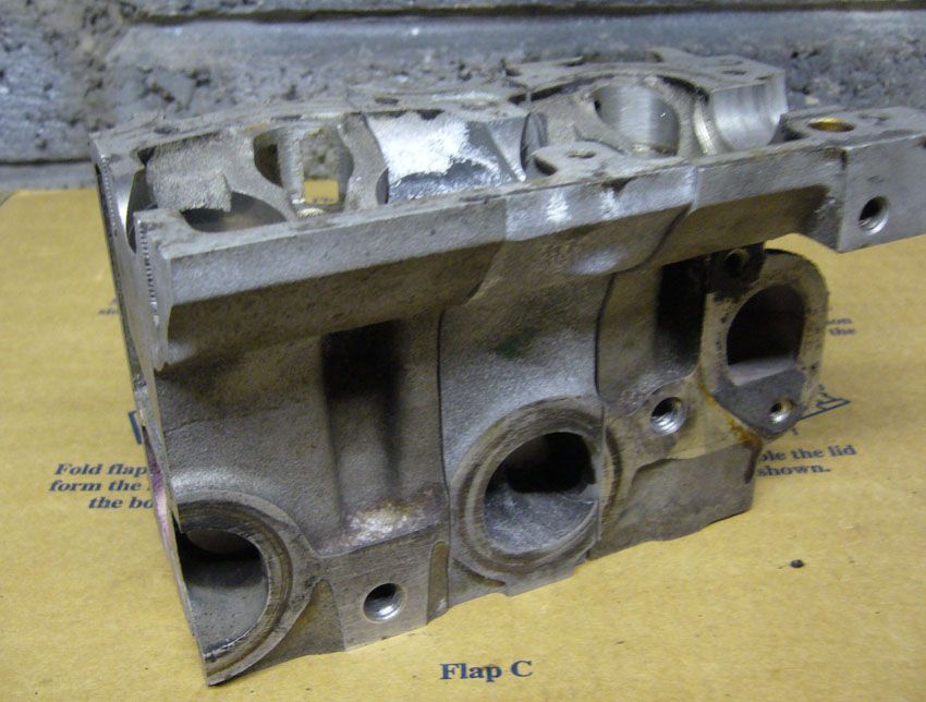
The second section shows this:
The port has a very fast transition from the seat (left hand side) to the floor of the port, although compared to some 16v heads of the same vintage (and newer) it's much better.
This is probably driven by:
1. The need to keep the port diameter at a reasonable size to prevent choking
2. The need to keep the overall head height as low as possible, probably to make engine packaging across a range of cars easier.
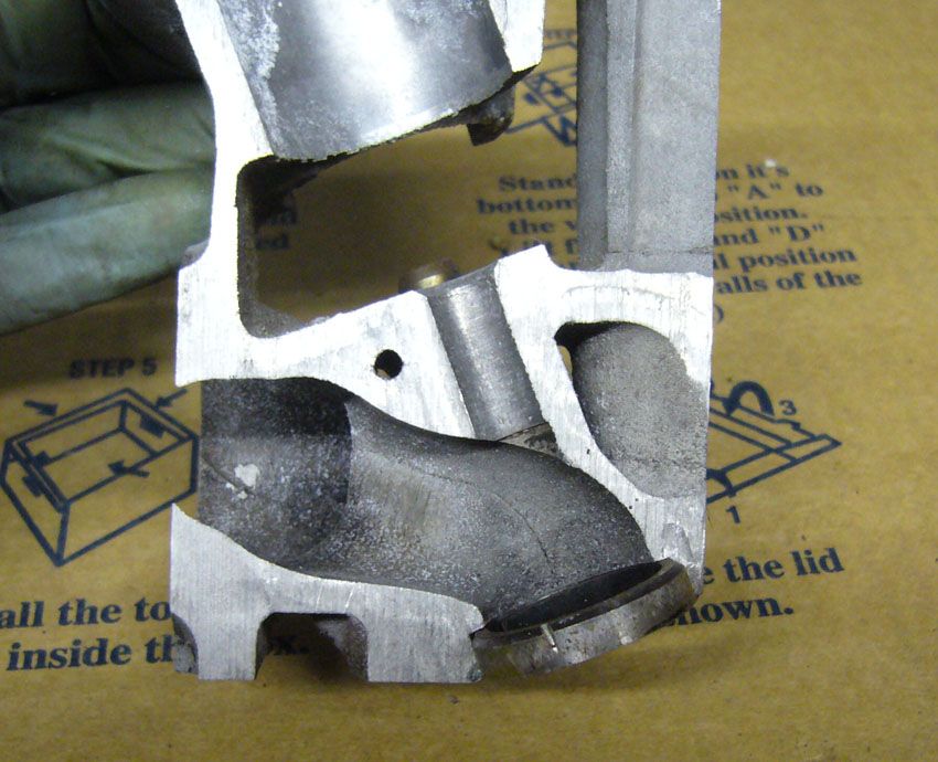
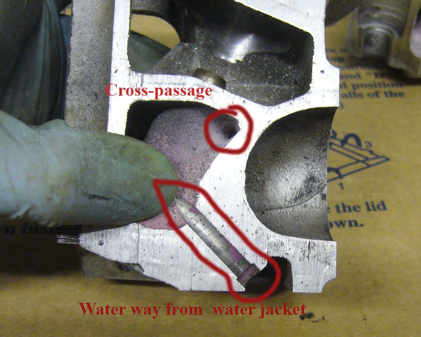
The other item of note is the bump after the valve guide boss. If you look at the inlets you can see the port swoops down, gets shifted for the boss, then re-establishes.
Here, for the exhausts, the boss just carries on a bit further.
The reason for this top bump is this cross passage for the water.
The exhaust side of a head is always the hottest, so needs more cooling, preferably in the form of jets.
Jets, rather than normal, wide (relatively speaking) passages are useful as the high flow velocity creates a lot of turbulence, which helps to scavenge the surface better than a slower flow.
When they expand into larger passages they help mixing as well.
The cross passage is marked here:
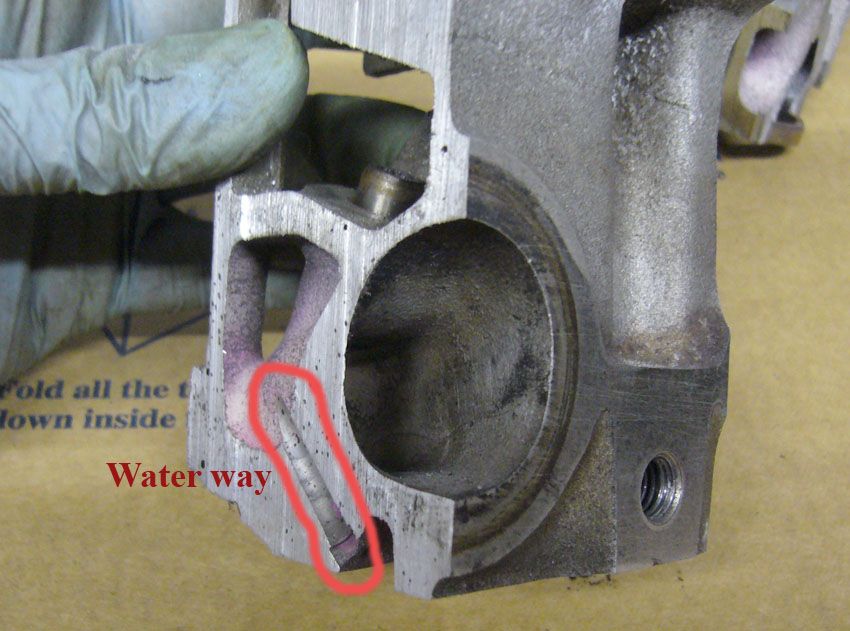
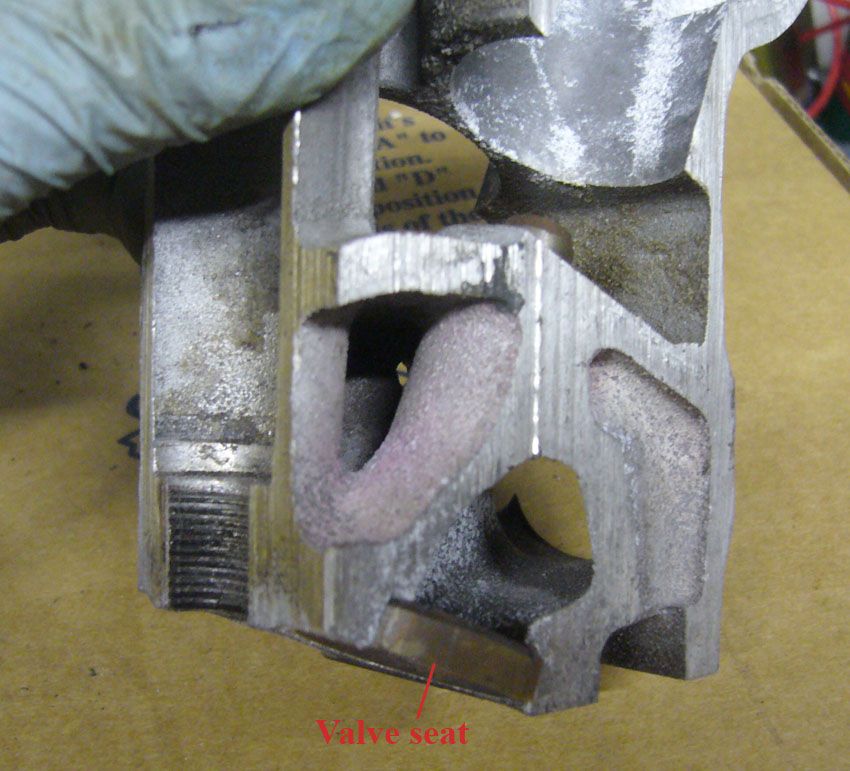
This is how it refers to the overall shape:
The mid-line of the port can be seen here, with it's waterway from the coolant passage clearly visible. This passage lines up with a hole in the head gasket to, presumably, let water have a preferential path to the block to mix the rather hot coolant with a cooler mass in the block jacket:
If those waterways were not there no.4 cylinder would get cooked, due to 1,2 and 3 pushing very hot water from around their exhaust ports down to it.
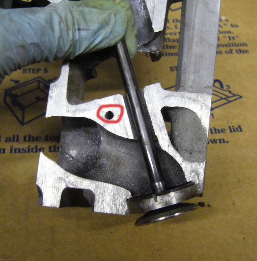
The flow path can perhaps be better visualised with a valve and a seat in place:
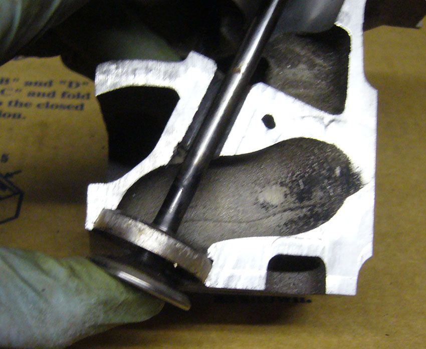
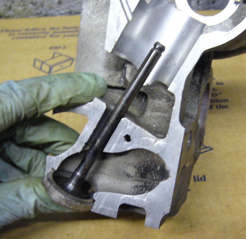
and here:
The individual ports from the seat to the exhaust gasket face are quite square, rather than trying to maintain a rounded profile and squishing them together to get to the round hole at the gasket face.
A square has a worse perimeter to area ratio than a circle, for a given required area, which means both more heat transferring surface (and thus more heat dumped to the head) and more wetted perimeter for the gas flow, meaning more pressure losses.
I assume that the packaging and cooling requirements took over in the development - it wasn't done on whim i'm sure.
I've modified a few of these now after cutting this up last year, and the rules i've given myself are:
1. Smooth & blend - the casting is rough (you can see the core shifts in some pictures)
2. Polish - shiny reflects heat (this helps gas velocity + the head itself) and prevents as much carbon build up as would otherwise happen.
3. Don't eat too much from the back of the valve guide boss - to prevent breaking in to the waterway. Measure, measure, measure and then measure again.
4. Cut back the bifrucation between the ports and knife edge it - i've not really shown this, but look at my head threads and it should be visible.
I've not made a silicone plug of the ports yet, but I have bought more RTV to do so, so I can get measurements for CFD.
http://forums.mg-rover.org/showthread.php?t=503432
This is the follow up, although the sections are not as exciting - Exhausts rarely are.
The sections are the opposites to the inlets in that thread:


The first section is the one on the cam pulley end.
The second section shows this:

The port has a very fast transition from the seat (left hand side) to the floor of the port, although compared to some 16v heads of the same vintage (and newer) it's much better.
This is probably driven by:
1. The need to keep the port diameter at a reasonable size to prevent choking
2. The need to keep the overall head height as low as possible, probably to make engine packaging across a range of cars easier.
The other item of note is the bump after the valve guide boss. If you look at the inlets you can see the port swoops down, gets shifted for the boss, then re-establishes.
Here, for the exhausts, the boss just carries on a bit further.
The reason for this top bump is this cross passage for the water.
The exhaust side of a head is always the hottest, so needs more cooling, preferably in the form of jets.
Jets, rather than normal, wide (relatively speaking) passages are useful as the high flow velocity creates a lot of turbulence, which helps to scavenge the surface better than a slower flow.
When they expand into larger passages they help mixing as well.
The cross passage is marked here:

This is how it refers to the overall shape:

The mid-line of the port can be seen here, with it's waterway from the coolant passage clearly visible. This passage lines up with a hole in the head gasket to, presumably, let water have a preferential path to the block to mix the rather hot coolant with a cooler mass in the block jacket:

If those waterways were not there no.4 cylinder would get cooked, due to 1,2 and 3 pushing very hot water from around their exhaust ports down to it.

The flow path can perhaps be better visualised with a valve and a seat in place:


and here:

The individual ports from the seat to the exhaust gasket face are quite square, rather than trying to maintain a rounded profile and squishing them together to get to the round hole at the gasket face.
A square has a worse perimeter to area ratio than a circle, for a given required area, which means both more heat transferring surface (and thus more heat dumped to the head) and more wetted perimeter for the gas flow, meaning more pressure losses.
I assume that the packaging and cooling requirements took over in the development - it wasn't done on whim i'm sure.
I've modified a few of these now after cutting this up last year, and the rules i've given myself are:
1. Smooth & blend - the casting is rough (you can see the core shifts in some pictures)
2. Polish - shiny reflects heat (this helps gas velocity + the head itself) and prevents as much carbon build up as would otherwise happen.
3. Don't eat too much from the back of the valve guide boss - to prevent breaking in to the waterway. Measure, measure, measure and then measure again.
4. Cut back the bifrucation between the ports and knife edge it - i've not really shown this, but look at my head threads and it should be visible.
I've not made a silicone plug of the ports yet, but I have bought more RTV to do so, so I can get measurements for CFD.
from the last news http://forums.mg-rover.org/showthread.php?t=723673&goto=newpost
via IFTTT
Libellés : IFTTT, the last news
publié par vb @ 12:27
0 commentaires
![]()

0 commentaires:
Enregistrer un commentaire
Abonnement Publier les commentaires [Atom]
<< Accueil